Back to turbo-machinery
 |
 |
Gas turbine engines today are ubiquitous in large scale power generation. Ships use gas turbine engines because of their high efficiency and power-to-weight ratio, gas turbines are used in industrial electrical power production because of their high efficiency, and modern military and large commercial aircraft all use turbofan jet engines because of their increased performance and efficiency at higher speeds and altitudes. Today though, with increasing fuel costs, and fuel as already the single largest operating expense for any airline, there is pressure to maximize the efficiency of these engines, which produces many challenges.
A basic gas turbine engine consists of 3 stages: Stage 1 is a compressor which compresses air into stage 2, the combustion chamber. Fuel mixed with the air is burned at high temperature and pressure in the combustion chamber, which is then expelled through stage 3, the turbine. The turbine collects energy from the escaping gas, which in turn powers the compressor as well as external components in most cases. In turbofan engines for example, some energy collected by the turbine from the escaping gas powers a fan via shaft, and some escapes through the rear to provide thrust.
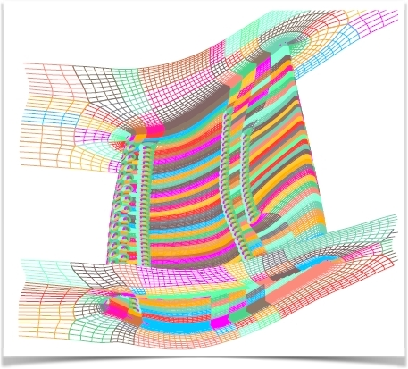
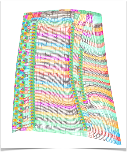
It is known from thermodynamic analysis that increased turbine inlet temperature leads to increased overall efficiency. Modern engines are designed to operate at turbine inlet temperatures around 1800-2000 K, but these temperatures greatly exceed the maximum allowable temperatures for metals. Even the most advanced metal alloys and ceramics available have their limits. In order to provide acceptable turbine life and safety, an effective means of cooling these components must be utilized. One method of providing cooling to turbine blades is the insertion of cooling holes on the leading edge of hollow turbine blades, through which cooler air is injected into the boundary layer on the surface of the blade. This is known as film cooling. Since air is diverted from the compressor stage of the engine though, it must be carefully balanced in order to minimize power loss from the compressor while providing the necessary cooling to protect the turbine. In this situation, finding this balance can be difficult. Design variations can be too difficult or expensive to test thoroughly. This is where computational fluid dynamics simulation can be.
Computational fluid dynamics (CFD) can be used to simulate flow and heat transfer in this type of environment, however there are several challenges to overcome in this case as well. The internals of a gas turbine present both complex geometries (multiple periodic turbine blades, blade tip clearances, cooling holes and passages) and complex physics (high speed, mixed temperatures, turbulence). Complex physics like this demand robust CFD codes, as well as robust grid generation. In such an environment, high-quality conformal hexahedral computational grids are preferred because they are verified to produce more accurate CFD results, but complex geometry like this can make generating grids a time consuming task.